|
Finding a Glitch Using Digital Persistence
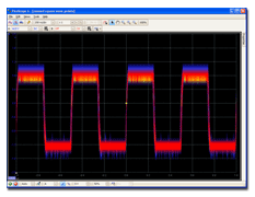
Persistence mode is designed to help you find rare events hidden in otherwise repetitive waveforms. In normal scope mode, such an event may appear on the display for a fraction of a second, too quickly for you to press the space bar to freeze it on the screen. Persistence mode keeps the event on the display for a predetermined time, allowing you to set up the trigger options to capture it more reliably.
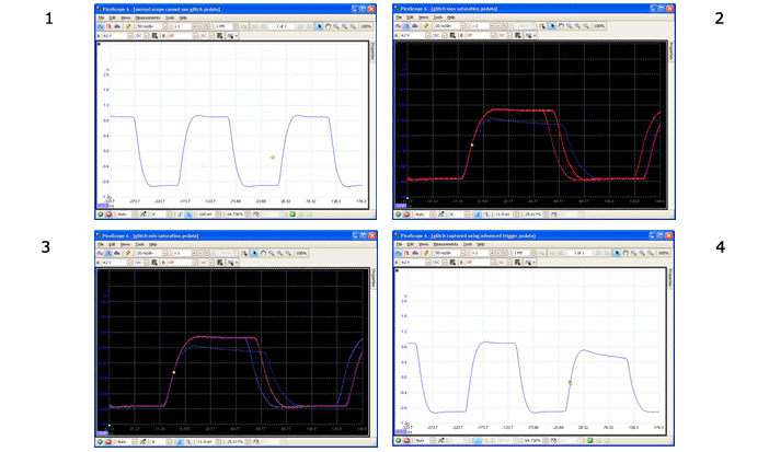
The example below shows how in four steps it is possible to capture a glitch using Digital Persistence.

1. We suspect that there are occasional glitches but we can see nothing wrong yet, so we shall use persistence mode to investigate.
2. Switching to Digital Persistence mode, our original scope view is replaced by a persistence view. Immediately, we can see three pulses with different shapes. At this point we have the Saturation control turned up to maximum to help us spot the various waveforms easily.
3. Now that we have found some glitches, we turn the Saturation control down to minimum. The waveforms are now darker but have a wider range of colours and shades. The most frequently occurring waveform is shown in red, and is the normal shape of the pulse. A second waveform is drawn in light blue to show that it occurs less frequently, and it tells us that there is an occasional jitter of about 10 ns in the pulse width. The third waveform is drawn in dark blue because it occurs less frequently than the other two, and indicates that there is an occasional runt pulse about 300 mV lower in amplitude than normal.
4. Persistence mode has done its job. We have found our glitches. To examine them in more detail we now switch back to normal oscilloscope mode and use the advanced triggering and automatic measurement functions built in to PicoScope. We set up an advanced pulse-width trigger to look for a pulse wider than 60 ns. PicoScope then finds the runt pulse straight away. We can now add automatic measurements or drag the rulers into place to analyse the runt pulse in detail.
|


